Ocean and Wave Energy
Why is the Northwest a promising area for using wave energy as a source of energy?
According to the US Department of Energy (Reference 8), the northwestern coast of the United States is one of the wave-power rich areas of the world. They estimate that wave energy could produce 40–70 kilowatts (kW) per meter of coastline, averaging about 1.6 Mw per 100 ft. The map below illustrates the energy generation potential of the US coastal areas. The ocean off the Pacific Northwest coast brings in most of the weather affecting the region and contains a lot of energy. The Oregon coast also has good access to transmission lines.

Figure 1 Renewable Northwest Project
How does wave energy supply us with electricity?
Generically, these devices take advantage of the vertical and/or horizontal motion of the waves to move a mechanical device that is connected to some type of generator.
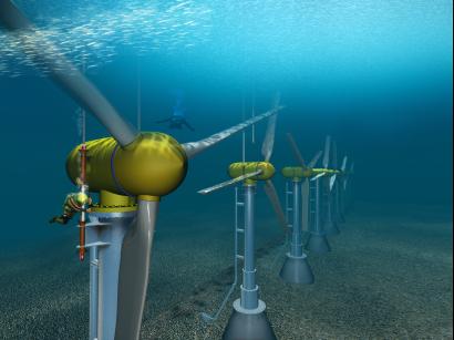
Underwater turbines
As with air wind turbines, there are horizontal axis turbines that use the water flowing past to drive the blades which convert the rotational energy to electrical energy. Depths are on the order of 60 to 100 feet. Similar to horizontal wind turbines, but smaller in size. Blade size is ¼ of that needed for equivalent wind turbine. (References 3, 8)

Figure 2 – Argonne National Laboratory
Floats, Buoys, and Pitching Devices
These use the rise and fall of the ocean swells to drive hydraulic pumps. The Aquabuoy is one example. (References 8, 10)

Figure 3 –AquaEnergy Group Ltd.

Figure 4 –Argonne National Laboratory
Oscillating Water Column
These generate electricity at the shore using the rise and fall of water within a cylindrical shaft. The rising water drives air out of the top of the shaft, powering an air-driven turbine. (References 4, 8, 21)

Figure 5 –BBC
Point Absorber
A point absorber is a floating structure with components that move relative to each other due to wave action (e.g., a floating buoy inside a fixed cylinder). The relative motion is used to drive electromechanical or hydraulic energy converters. (Reference 16)

Figure 6 – Argonne National Laboratory
Tidal Barrage or Dam
As the tide flows in and out, water level becomes uneven on either side of the dam. The higher head side is then used to direct the collected water to low head turbines for generating electricity. To be effective, the difference between high and low tides should be at least 16 feet. (References 3, 22) Click for animation illustrating principle.
Attenuators
Attenuators are long multisegment floating structures oriented parallel to the direction of the waves. The differing heights of waves along the length of the device causes flexing where the segments connect, and this flexing is connected to hydraulic pumps or other converters. (Reference 16)

Figure 7 – Argonne National Laboratory
Tapered Channel or Overtopping Device
These concentrate waves and drive them into an elevated reservoir, where power is then generated using hydropower turbines as the water is released . The Wave Dragon is one example. The Seawave Slot Cone generator is another example with multiple reservoirs. Overtopping devices have reservoirs that are filled by incoming waves to levels above the average surrounding ocean. The water is then released, and gravity causes it to fall back toward the ocean surface. The energy of the falling water is used to turn hydro turbines. These floating platforms create electricity by funneling waves through internal turbines and then back into the sea. (References 4,8,14, 20)

Figure 8 - Wilfried Knapp, Technische Universitat Munchen
Pendulor
The pendulor wave-power device consists of a rectangular box, which is open to the sea at one end. A flap is hinged over the opening and the action of the waves causes the flap to swing back and forth. The motion powers a hydraulic pump and a generator. (Reference 4, 22)

Figure 9 – Schlumberger Excellence in Educational Development
Rubber Hose (Anaconda, Snake)
The water in the tube moves in synch with the outside wave motion and impacts a turbine in the end section. (Reference 15)

Figure 10 – New Scientist
Salter Duck
The duck ‘bobs’ up and down on waves and a special turbine inside converts this movement into electricity. Salter Duck(s) are large in size and are arranged in set patterns to take advantage of wave formations. (References 12, 13)

Figure 11 – V. Ryan
Tidal Bridges and Fences
Similar to vertical axis wind turbine approach. Water flow turns blades or turnstiles which are connected to generators. (References 3, 9)

Figure 12- Blue Energy Canada & World Energy Research
References
Renewables Home - Virtual Nuclear Tourist - Tuesday March 29, 2011