Emergency Feedwater
Systems
Function
The Emergency Feedwater System in pressurized nuclear power plants may
also be named Auxiliary Feedwater. The purpose of this system is to continue supplying
enough makeup water to the steam generator to continue removing heat from the reactor
after the reactor has been shutdown. When the reactor is shutdown the feedwater pumps are
not normally used. No credit is taken for the normal feedwater pumps during accident and
transient analyses because the assumption is made that their power source, a non-safety
system, is unavailable.
Major Components
Major system components include:
- Non-safety and safety grade water sources
- The non-safety water source, typically called the Condensate Storage Tank, may hold nominally 150,000 gallons. In the event that source is unavailable, there is also
a
- Safety grade water source typically called Emergency Service Water,
Ultimate Heat Sink. This water source is usually the river, lake, sea, or ocean. This
source is considered a last resort as a water source for the steam generators because the
chemical purity is not as high as normally desired.
- Turbine driven emergency feedwater pump to pump water from the source to
the steam generator, in the event there is sufficient steam available and if AC power is
unavailable. This pump often has a low capacity of 200 to 400 gallons per minute. As with
any turbine-driven pump there are lubricating oil systems, governor systems, and cooling
systems (e.g. to cool the oil).
- Motor driven emergency feedwater pump (1 or more) which has electric
power supplied from a safety grade source as a diesel generator. This pump often has a low
capacity of 200 to 400 gallons per minute. As with any motor-driven pump there are
lubricating oil systems and cooling systems (e.g. to cool the oil).
- Various motor valves are provide for - (1) throttling of water flow to
the steam generators since this system is normally used when the reactor is shutdown for
refueling and started up after a refueling, and (2) isolation of pumps and other equipment
for preventive or corrective maintenance.
- Systems usually use check valves (non-return) which prevent backflow to
protect the pumps usually.
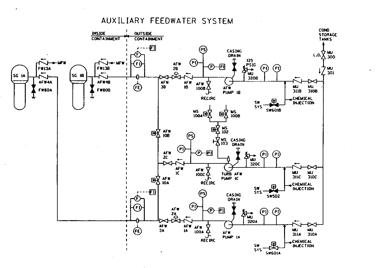
Sample System Diagram
A typical Auxiliary Feedwater System flow diagram is
illustrated below:

Copyright © 1996-2006. The Virtual Nuclear
Tourist. All rights reserved. Revised: January 4, 2006.

