The PWR Reactor Coolant System has three (3) major functions:
Major Components and Simplified Sketch
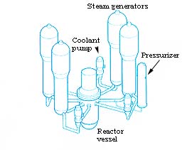
The Reactor Coolant System consists of the following major components other than the reactor:
| The sketch below illustrates the Reactor Coolant System's major components- Reactor Vessel, Steam Generators, (Reactor) Coolant Pump, and Pressurizer. Click to see a 51K detailed drawing of the RCS with parts identified. |
|
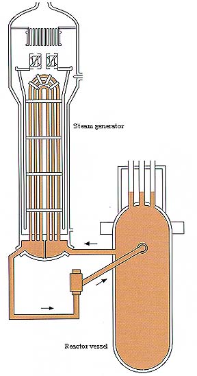
| The diagram below illustrates the flow paths involved and relative positions of the Reactor, Steam Generator, and Reactor Coolant Pump (not identified). This diagram also nicely illustrates the inside of the steam generator with the U tubes, divider plate between the "hot" and "cold" parts of the bottom head of the steam generator. |
|
Functions of Major Components
 |
Steam Generator | The vertical Steam Generator as shown has over 3000 tubes. The tubes are in an upside down U shape. Reactor coolant from the hot leg comes in the bottom, passes through the inside of the tubes. The reactor coolant water cools from about 590-600F to 520-530F. The heat passes through the tubes to the "secondary side" where water supplied from the feedwater system is heated from about 425F to about 510F. This water is converted to steam. In the upper part of the steam generator are moisture-separators which remove the water in the steam and divert it back into the lower part of the steam generator. Click the figure to see a 43K detailed drawing of the Steam generator with parts identified. |
| Graphics courtesy Westinghouse | ||
 |
Pressurizer | The Pressurizer in a Pressurized Water Reactor design maintains the pressure through heaters mounted in the bottom and a spray nozzle mounted in the upper part of the vessel. Also included are safety valves which lift if pressure is too high and automatic relief valves (also called Power Operated Relief Valves) designed to lift before the safety valves lift. Pressure is normally maintained in a range of 2200 to 2250 pound per square inch. This corresponds to a temperature of about 650F. Click the figure to see a 26K detailed drawing of the Pressurizer with parts identified. |
| Graphics courtesy Westinghouse | ||
|
|
Reactor Coolant Pump | The Reactor Coolant Pump circulates the water through the Reactor Coolant System. These pumps generally pump at a rate of almost 100,000 gallons per minute. Click the figure to see a 51K detailed drawing of the Reactor Coolant Pump with parts identified. |
| Graphics courtesy Westinghouse | ||
 |
Reactor | The Reactor is intended
to produce heat in all reactor designs. Water usually is
supplied to the reactor at about mid-height, then flows
downward, then turns at the bottom where it is directed
upwards, passing past the fuel assemblies, removing heat
as the water passes by. The CANDU design is different in that water enters, passes through, and leaves in the horizontal direction only. Click the figure to see a 54K detailed drawing of the Reactor with parts identified. Click this link to see a 45K detailed drawing of a fuel assembly with parts identified. |
| Graphics courtesy Westinghouse |
Additional Comments
For additional illustrations and discussion of these components and the reactor cooling system, please go to other pages on the site - More on Reactor Cooling Systems - PWR Cycle. See the refueling page for photos showing disassembly of the reactor.
Copyright © 1996-2004. Joseph Gonyeau, P.E.. The Virtual Nuclear Tourist. All rights reserved. Revised: March 15, 2001.