Service or Cooling Water Systems
Service Water Systems at any power plant has one major function
This system is referred to by a variety of names - Service Water, Cooling Water , Salt Water. Sometimes the system is broken into separate building systems as Turbine Building, Auxiliary Building, Reactor Building. Often the system is broken into safety and non-safety portions. For a number of plants the safety portion is referred to as the Essential Service Water System. The equipment in the safety portion of the system is powered by independent sources, e.g. diesel-driven pumps and diesel generators to supply electrical power.
Major Components
Normal and Emergency Intake (Supply) Basins
Water is supplied from an abundant source - river, lake, sea, or ocean - to a storage basin which, in turn, supplies the large pumps.
Emergency Intake Pipe
An emergency intake pipe may be used to provide a direct alternate path to the emergency portion of the system if the normal flow path is unavailable.
Emergency or Safeguards Traveling Screens
These are large steel screens up to 30 feet long that rotate and filter out larger debris that passes through the trash racks.
Service Water Pumps
For many plants there are an average of 3 pumps for single unit plants and 5 pumps for dual unit facilities. These pumps each supply water at about 10,000 - 15,000 gallons per minute to a two (2) header system. Often the pumps are broken into safety and non-safety classes. For safety-related components this method assures redundancy.
Heat Exchangers or Coolers
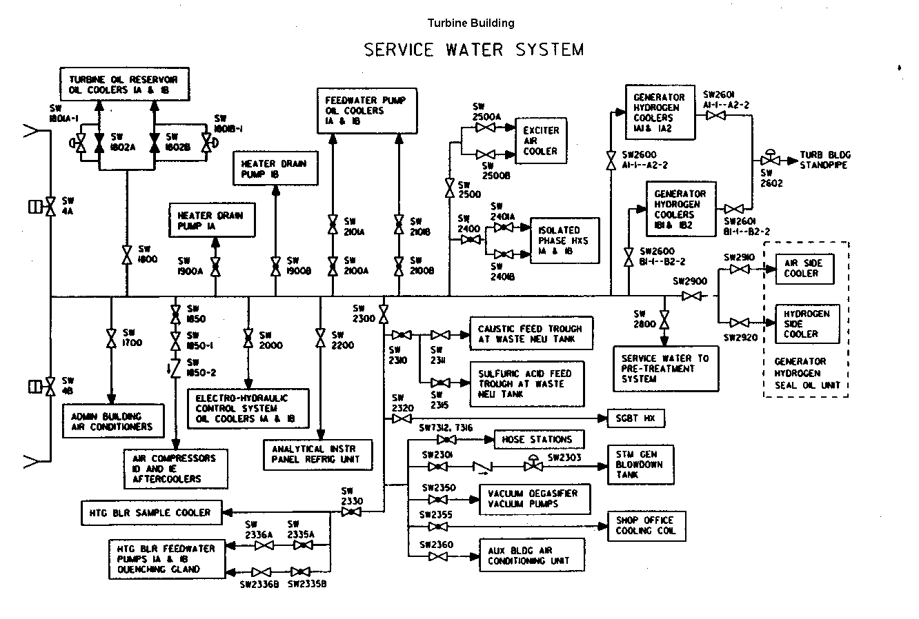
Components cooled or served by the Service Water System include:
- Generator Hydrogen Gas Cooler
- Stator cooling
- Generator exciter cooler
- Air compressor aftercooler
- Component Cooling Heat Exchanger
- Containment Fan Cooler Units
- Feedwater Pump Oil and Motor Coolers
- Condensate Pump Oil and motor Coolers
- Turbine Oil Cooler
- Heater Drain Pump Oil and Motor Cooler
- Diesel Generators
- Circulating Pump Seal Water
In addition, the Service Water system may provide the backup water source to the emergency feedwater pump.
Simplified Diagrams
The diagram below illustrates the major flow paths for a typical ServiceWater System in the Turbine Buiolding where major nonessential heat loads are cooled.

Copyright © 1996-2006. The Virtual Nuclear Tourist. All rights reserved. Revised: January 4, 2006.