Pressurized Water Reactor (PWR)
PWR is the abbreviation for the Pressurized Water Reactor. These reactors were originally designed by Westinghouse Bettis Atomic Power Laboratory for military ship applications, then by the Westinghouse Nuclear Power Division for commercial applications. The first commercial PWR plant in the United States was Shippingport, which operated for Duquesne Light until 1982.
In addition to Westinghouse, Asea Brown Boveri-Combustion Engineering (ABB-CE), Framatome, Kraftwerk Union, Siemens, and Mitsubishi have typically built this type of reactor throughout the world. Babcock & Wilcox (B&W) built a PWR design power plant but used vertical once-through steam generators, rather than the U-tube design used by the rest of the suppliers. Refuelings are done with the plant shutdown.

Reproduced by permission
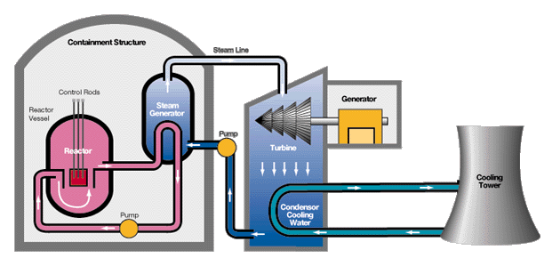
The Pressurized Water Reactor (PWR) has 3 separate cooling systems. Only 1 is expected to have radioactivity - the Reactor Coolant System.
The Reactor Coolant System, shown inside the Containment, consists of 2, 3, or 4 Cooling "Loops" connected to the Reactor, each containing a Reactor Coolant Pump, and Steam Generator. The Reactor heats the water that passes upward past the fuel assemblies from a temperature of about 530F to a temperature of about 590F. Boiling, other than minor bubbles called nucleate boiling, is not allowed to occur. Pressure is maintained by a Pressurizer (not shown) connected to the Reactor Coolant System. Pressure is maintained at approximately 2250 pounds per square inch through a heater and spray system in the pressurizer. The water from the Reactor is pumped to the steam generator and passes through tubes. The Reactor Cooling System is expected to be the only one with radioactive materials in it. Typically PWRs have 2, 3, or 4 reactor cooling system loops inside the containment.
In a Secondary Cooling System (which include the Main Steam System and the Condensate-Feedwater Systems), cooler water is pumped from the Feedwater System and passes on the outside of those steam generator tubes, is heated and converted to steam. The steam then passes through the a Main Steam Line to the Turbine, which is connected to and turns the Generator. The steam from the Turbine condenses in a Condenser. The condensed water is then pumped by Condensate Pumps through Low Pressure Feedwater Heaters, then to the Feedwater Pumps, then to High Pressure Feedwater Heaters, then to the Steam Generators.The diagram above simplifies the process by only showing the condenser, a pump, and the steam generator.
The condenser is maintained at a vacuum using either vacuum pumps or air ejectors. Cooling of the steam is provided by Condenser Cooling Water pumped through the condenser by Circulating Water Pumps, which take a suction from water supplied from the ocean, sea, lake, river, or Cooling Tower (shown). A discussion of cooling towers is provided in the photo section.
Information on the types of systems used in each type of PWR reactor and plant design may be found by clicking one of the following links to the specific NRC plant information book:
As in the BWR case, sections A, B, C, D and E provide complete information.
For more complete drawings and discussion, refer to PWR Cycle.
Copyright © 1996-2001. Joseph Gonyeau, P.E.. The Virtual Nuclear Tourist. All rights reserved. Revised: March 15, 2001.